
 EN
EN
 AR
AR
 BG
BG
 HR
HR
 CS
CS
 DA
DA
 NL
NL
 FI
FI
 FR
FR
 DE
DE
 EL
EL
 HI
HI
 IT
IT
 JA
JA
 KO
KO
 NO
NO
 PL
PL
 PT
PT
 RO
RO
 RU
RU
 ES
ES
 SV
SV
 CA
CA
 TL
TL
 IW
IW
 ID
ID
 SR
SR
 SK
SK
 UK
UK
 VI
VI
 HU
HU
 TH
TH
 TR
TR
 FA
FA
 AF
AF
 MS
MS
 GA
GA
 HY
HY
 BN
BN
 MN
MN

How Does a 12V to 24V Converter Boost Voltage for Truck and Heavy Equipment Electronics?
The Voltage Divide in Mobile and Heavy Equipment Power Systems
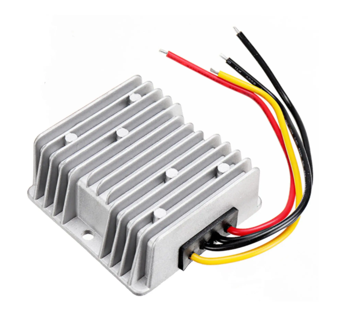
Walk through a truck yard, a marine service center, or a heavy equipment maintenance depot, and a curious electrical reality reveals itself. Some vehicles and machines run their core electrical systems on 12 volts. Others run on 24 volts. The split is historical, regional, and application-driven. Many North American light trucks, vans, and passenger vehicles have standardized on 12-volt systems, while heavy commercial trucks, buses, agricultural tractors, construction machinery, and marine vessels frequently operate on 24-volt systems to reduce current draw for high-power starting, lighting, and hydraulic pump circuits. The problem arrives when a 24-volt vehicle needs a piece of electronics that is only available or only affordable in a 12-volt version, or the reverse, when a fleet of 12-volt trucks needs to power 24-volt communication radios, GPS navigation units, diagnostic tools, or specialized work lighting. The voltage does not match, and simply wiring a 12-volt device into a 24-volt electrical system will destroy it, often instantly and sometimes spectacularly. This is the practical gap that a DC to DC boost converter fills. A 12V to 24V converter takes the nominal 12-volt input from a vehicle's battery and electrical system and raises it to a stable, regulated 24-volt output suitable for powering electronics designed for that higher voltage. The device is not a transformer in the traditional alternating current sense. It is a switching power supply that manipulates direct current through a high-frequency switching process, and understanding how it does this, and how to select and install one correctly, is essential knowledge for anyone maintaining or modifying a mixed-voltage fleet.
The Core Technology and How DC to DC Boost Conversion Works
A transformer cannot boost direct current voltage because a transformer requires a changing magnetic field, and direct current produces a static field. The boost converter solves this problem by turning the steady direct current input into a rapidly switching current, effectively creating its own changing magnetic field inside a compact inductor. The process begins with a switching transistor, typically a metal-oxide-semiconductor field-effect transistor, that opens and closes at a high frequency, often tens or hundreds of kilohertz. When the switch closes, current flows from the input through an inductor, and the inductor's magnetic field builds, storing energy. When the switch opens, the magnetic field collapses, and the inductor fights the change in current by generating a voltage spike in series with the input voltage. This combined voltage, the input voltage plus the inductor's discharge voltage, is directed through a diode into an output capacitor. The capacitor smooths the pulsed output into a stable direct current voltage. The output voltage is regulated by controlling the duty cycle of the switch, the ratio of on-time to off-time. A longer on-time builds more energy in the inductor and produces a higher output voltage. A shorter on-time produces a lower output voltage. A feedback circuit monitors the output and adjusts the switching duty cycle in real time to maintain the desired output voltage even as the input voltage fluctuates and the load changes. This entire cycle happens thousands of times per second. The result is a steady 24-volt output from a 12-volt input, with the output voltage actively regulated against the variations in battery voltage that occur during engine cranking, alternator charging, and accessory load changes.
Key Specifications and the Relationship Between Voltage, Current, and Wattage
Selecting a boost converter requires understanding the relationship between the numbers printed on the specification sheet and the actual demands of the equipment to be powered. The input voltage range specifies the minimum and maximum voltage the converter will accept while still producing a regulated output. A vehicle's 12-volt system is not a constant 12 volts. It dips during engine cranking, rises during heavy alternator charging, and can spike during load dumps when a large accessory is disconnected. A converter with a wide input range, perhaps 9 to 16 volts, accommodates these fluctuations without shutting down or producing an erratic output. The output voltage specification indicates the regulated voltage the converter delivers. A quality converter holds this voltage stable within a tight tolerance across the full range of input voltage and output load conditions. The power rating, expressed in watts, is the fundamental capacity limit of the converter. A converter rated for 240 watts can deliver a maximum continuous load at 24 volts of 10 amperes. This relationship is fixed. As the step-up ratio increases, the available output current decreases for a given input current, because the converter cannot create power, only convert it, and some power is lost as heat in the conversion process. The efficiency rating, typically expressed as a percentage, indicates how much of the input power reaches the output. A converter with high efficiency converts more of the input energy into usable output and wastes less as heat, an important consideration for a device mounted in an enclosed vehicle compartment or an engine bay.
Protection Features That Safeguard the Converter and Connected Equipment
A boost converter sits in the electrical path between a vehicle's battery and sensitive electronic equipment, and its failure mode can involve either or both. Comprehensive protection features are not optional add-ons. They are the difference between a converter that sacrifices itself to protect the load and a converter that takes the load with it when it fails. Input reverse polarity protection prevents damage if the installer momentarily connects the positive and negative input wires backward during installation. This protection typically takes the form of a diode or a MOSFET-based circuit that blocks current flow when the polarity is reversed. Over-temperature protection monitors the internal temperature of the converter's switching transistor and transformer. If the temperature rises beyond a safe threshold, typically due to overload, high ambient temperature, or blocked ventilation, the converter either reduces its output power or shuts down entirely until the temperature recovers. Output over-voltage protection monitors the output and disables the converter if the output voltage exceeds a preset limit due to a component failure in the feedback or regulation circuit. Without this protection, a failed converter could deliver an unregulated voltage far higher than 24 volts to the connected equipment. Output short-circuit protection detects a short across the output terminals and shuts down the converter to prevent the short from drawing destructive levels of current through the output circuit. These protection features operate automatically and recover either automatically or after a power cycle, protecting both the converter and the expensive electronics it powers.
Installation Best Practices and the Wiring Considerations
A boost converter's performance and service life are determined as much by its installation as by its internal design. The input wiring carries higher current than the output wiring because the input voltage is lower for the same power level. A converter delivering 240 watts at 24 volts draws roughly 20 amperes from the 12-volt source at full load, plus additional current to cover conversion losses. The input wire gauge must be sized for this maximum input current over the entire length of the wire run, accounting for the round-trip distance from the battery to the converter and back to the battery through the chassis ground. Voltage drop on the input side has a compounding effect. As input voltage drops due to undersized wiring, the converter must draw more current to deliver the same output power, which increases the voltage drop further. A short, heavy-gauge input wire run minimizes this effect. Fuse protection is required on the input side, placed as close to the battery connection as practical, to protect the wiring against a short circuit upstream of the converter. The output side may also benefit from a fuse sized to the maximum rated load of the connected equipment. The converter's mounting location must provide adequate airflow across the heat sink fins. A converter mounted in a sealed, unventilated compartment will eventually overheat and shut down, even if it is operated well within its power rating. The mounting surface, if it is part of the vehicle's structure, should be flat, clean, and thermally conductive if the converter's heat sink is designed to dissipate heat through the mounting base.
Manufacturing Quality and the Reliability Demands of Commercial Vehicle Environments
A boost converter installed in a truck, a piece of construction equipment, or a marine vessel operates in an environment that punishes electronics. Vibration from the engine and the road surface shakes every solder joint and component connection. Temperature extremes from cold-soaked winter mornings to engine bay heat soak cycles stress every capacitor and semiconductor. Dust, moisture, and in marine applications, salt spray, corrode exposed terminals and conductive traces. The converter's ability to survive these conditions and continue delivering a stable output depends on the quality of its design and manufacturing. The printed circuit board should be conformally coated to resist moisture and contaminant ingress. The enclosure should be mechanically robust, with strain relief on the input and output wiring connections to prevent vibration fatigue at the solder joints. The internal components, particularly the electrolytic capacitors, should be rated for high-temperature operation and long service life. RCNUN manufactures DC to DC converters with attention to these environmental demands, producing units where the circuit design, component selection, and assembly quality reflect the realities of mobile and heavy equipment use. For a fleet manager, an equipment upfitter, or a commercial vehicle operator, the converter's reliability translates into uptime for the electronics that depend on it. A communication radio that loses power during a critical transmission, a GPS unit that reboots during navigation, or a work light that flickers out on a night job site are failures that a quality converter, properly specified and installed, prevents. The converter is a small box mounted out of sight, but its presence or absence defines whether the 24-volt electronics in a 12-volt vehicle function as intended or remain dark, silent, and useless.
Recommended Products
Hot News
-
Application Advantages of Non-Isolated BUCK Converters Compared to Isolated Step-Down Converters
2024-01-23
-
DC-DC Converters Showcase Remarkable Advantages in Outdoor Off-Grid Applications
2024-01-23
-
DC to DC Battery Charger - Wide input and Noise immunity for dual battery system applications
2024-01-19